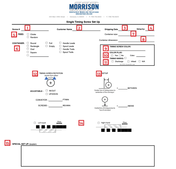
Our Timing Screw Setup Sheets are specific to the type of system you are running and are essential to that system as they contain all the information needed to properly setup and run the timing screw component. Below is a breakdown of the information that appears on these sheets and how that information can assist you while running a system.
We have 3 types of standard setup sheets: single, dual, and stacked. For this example, we will use our Single Timing Screw Setup Sheet to explain the sections of the sheet and illustrate why this form is a helpful tool for you.
Let’s take this sheet field by field:

- Screw #
- The screw number is assigned by Morrison to identify the specific screw in use. This information is valuable if for any reason you have a specific question regarding that screw.
- Customer Name
- This information should look familiar as it is the name of your company or organize.
- Shipping Date
- This field contains the date your system was shipping from our facility to yours.
- Setup By
- This section notes who set the system up in our facility as we are dedicated to your success while running the system. Included in all of our products is Support Built In® which is our personal customer service program for any general questions you may have or technical support you may need.
- Feed
- The feed section denotes whether the screw is designed for choke or random feed. A choke fed system is a system that has a preloaded backlog when the system starts. A random fed system is where there is not a constant backlog of containers, and the screw feeds the containers in randomly.
- – 8. Container, Container Size, Container Dimension
- The container, container size, and container dimension tell us the exact container that the screw is designed for. There are boxes to fill in the shape of the container, whether it is full or empty, and if the container has a handle or spout and which way the handle or spout is facing.
- – 11. Timing Screw Color, Color Plug, Timing Marks
- The timing screw color, color plug, and timing marks help describe the individual screw more. The color denotes the color of the screw. Color plugs indicate left and vs right hand side, location of the screw in the system, and container identification. Timing marks provide insight on whether the system is timed correctly and can also aid in returning the system to the proper timing position.
- Timing Screw Rotation
- The timing screw rotation section shows arrows indication left or right for which way the screw will turn. There are also checkboxes noting if the screw is adjustable in/out and up/down. The conveyor speed and screw speed are also noted in the shown dimensions.
- Setup
- The setup portion of the timing screw setup sheet notes the centerline of the timing screw to the centerline of the conveyor in inches and the centerline of the timing screw to the top of the conveyor in inches.
- Left Hand or Right Hand
- The Left Hand or Right Hand section of the setup sheet contains checkboxes to denote if the system is a Right Hand system or a Left Hand system. The difference between the two is noted in which side the screw is placed on.
NOTE: This section looks different on the dual setup sheet and displays accurate information about the system as it pertains to a dual setup.
 This portion of the setup sheet denotes which way the screw is rotating for turner and shingle screws. The screw will rotate either clockwise or counterclockwise. The left image denotes which screw should be placed on which side of the system.
- The special setup portion of the setup sheet has a box for notes where any explanation needed for the system that is not noted above can be placed.
Our setup sheet, which can be found in your Morrison User Manual, is designed to help you make setup a smooth process and to be there when you need a reference or guide on the timing screw for the future. On the off chance a system is running incorrectly, our setup sheet can aid you in getting your system back up and running.


